
How the Clickit Critter works:
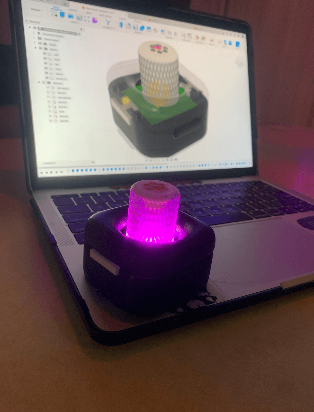
Start up animation:
The Clickit Critter is interactive wireless Bluetooth controller for manipulating the camera view in Fusion 360 and other softwares. This project focused on enhancing skills in PCB fabrication, 3D modeling and printing, surface finishing, and user interface design.
Using Fusion 360, a 3D model was created for electronic components and the tangible interface, designing an enclosure with joystick-type interface, momentary push buttons, ergonomic fit, disassembly via M3 screws, and USB connectivity. This involved enhancing skills in PCB fabrication, 3D modeling and printing, surface finishing, and user interface design. 3D printing (FDM/SLA) was then used to create high-quality prints from these models, preparing and slicing prints using Ultimaker Cura, selecting appropriate printers, and inspecting prints for quality.


The Clickit Critter's PCB was soldered using SMD and THT techniques. The soldering process involved using tools like a reflow oven, tweezers, pliers, solder paste stencil, and various electronic components. Arduino IDE was used to program the ESP32, configure the panel, and customize button functions and LED colors. This step required installing libraries, configuring device settings, and finalizing the code for the project.


The following steps involved finishing and assembling a 3D-printed enclosure with an emphasis on surface refinement and final construction. Surface Finishing included sanding, priming, painting, and clear-coating the prints, using tools like sandpaper, a paint shaker drill, and materials such as primer, colored spray paint, and clear coat spray paint. This step emphasized thorough sanding to remove layer lines and defects, as well as using a soldering iron with a heat set insert attachment to insert heat set inserts into the enclosure. Final touches included applying a small amount of colored epoxy resin to the inset design on the joystick knob for a customized look. Final Assembly focused on assembling the finished parts using tools like a screwdriver, hex key, and toothpicks, along with materials like CA glue and non-slip feet. The process involved placing the PCB into the bottom half of the enclosure, attaching the top, adding buttons and the joystick knob, and securing everything with screws. Non-slip feet were then added to the bottom corners of the enclosure for stability, resulting in a professionally finished and assembled product ready for use.


PCB Design Practice involved designing a PCB from an existing schematic to create a compact, functional circuit board. To do this, hardware, software, tools, and materials were gathered, then access to the PCB design was gained by being added to the development group. The circuitry in the schematic file and the PCB design file was familiarized with, then components were moved around to create a rough layout. Components were connected with traces, ground and power planes were created using vias, and errors were checked before documenting the work with 2D and 3D renderings.
